
8. Data architecture
In this section we will present the data architecture chosen for the Vertical Cabling data. The introduction will be kept very high-level and the detailed fields of each entity will be presented in the Data Structure section below.
Our main objectives and guidelines are:
- be able to model the most complex use cases of vertical cabling infrastructures in multi-dwelling units
- keep the smallest possible set of data to perform that task.
- not store any privacy relevant data (e.g. personal data) (if possible)
- limit the number of unstructured text fields to a minimum
- keep a history of the evolution of the vertical cabling situation
8.1. Vertical Cabling Data Architecture
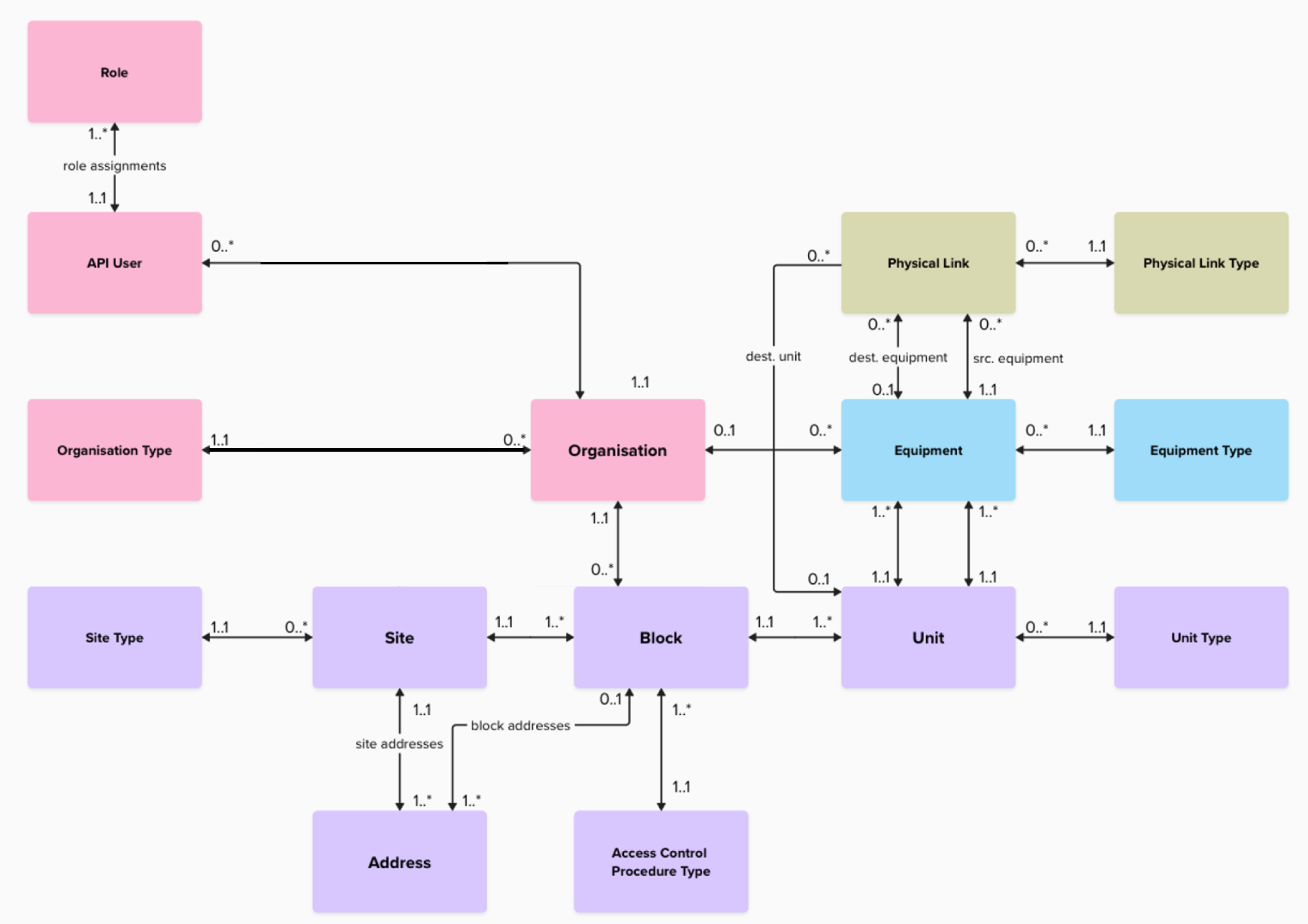
|
The background colors of the above image are to be interpreted as:
|
Definitions
In the diagram you will find two things:
- boxes: that represent entities in the database. The entities will have the same name as the boxes but in snake case
- edges that link two boxes: the named edges represent junction tables
You will find below a description of each entity that is part of the data architecture:
| Entity | Description |
|---|---|
| Address |
An address that is available in the system. Addresses have two possible sources:
|
| Site Type |
A site type denotes the specificity of the site with respect to the type of habitation:
|
| Unit Type |
A unit type describes the purpose of the unit:
|
| Access Control Procedure Type |
The access control procedure type, indicates how the access to the building is provided:
|
| Site | A Site is building or group of blocks. Depending on the size and complexity of the Site, it can have multiple addresses attached to it. |
| Block | A Block is a part or entirety of a Site to which multiple units can be attached to. |
| Unit | A Unit, is either an apartment / office / or any other subdivision of a Block (e.g. technical room, elevator, parking, common room). |
| Equipment | An equipment can be a specific NTP, a floor distributor, a wall socket, a cabinet, or any other equipment on which a physical link can be terminated. |
| Equipment Type | An equipment type (NTP, floor distributor, wall socket, cabinet, …) is specific type of equipment that can be installed at the customer premises and on which a physical link can be terminated. |
| Physical Link | A physical link represents the physical link in between two equipments or an equipment and a unit. The physical link only indicates the presence or absence of a given Link Type, it does not indicate the quantity of cables connecting both units. |
| Physical Link Type | The Physical Link Type can be any type of physical link that can be used to connect two equipments together to deliver telecommunication services |
| Organisation Type |
A type of Organisation:
|
| Organisation |
An Organisation, represents a legal entity. This organisation can be:
|
| Role |
The different roles as defined in this document
|
| API User | A user of the system |
Below you will also find the description of the junction tables:
| Entity | Description |
|---|---|
| role assignments | A junction table that will keep track of the roles assigned to each user |
| site addresses | A junction table that will contain the link between the sites and their addresses |
| block addresses | A junction table that will contain the link between the blocks and their addresses |
8.2. Pictures
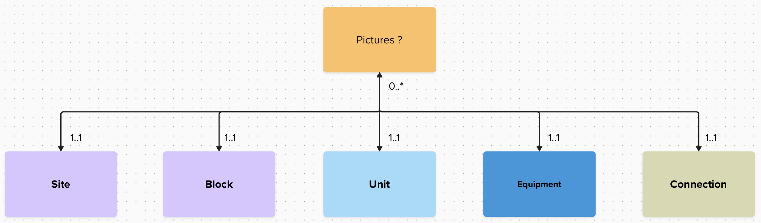
On top of the above vertical cabling data, pictures can also be attached to the sites / blocks / …
8.3. Data Structure and data dictionary
You will find below an excel file that defines and justifies each field stored in the RNCV:
No comments to display
No comments to display